Learning Objectives
Learning Objectives
By the end of this section, you will be able to do the following:
- Draw a circuit with resistors in parallel and in series
- Use Ohm’s law to calculate the voltage drop across a resistor when current passes through it
- Contrast the way total resistance is calculated for resistors in series and in parallel
- Explain why total resistance of a parallel circuit is less than the smallest resistance of any of the resistors in that circuit
- Calculate total resistance of a circuit that contains a mixture of resistors connected in series and in parallel
The information presented in this section supports the following AP® learning objectives and science practices:
- 4.E.5.1 The student is able to make and justify a quantitative prediction of the effect of a change in values or arrangements of one or two circuit elements on the currents and potential differences in a circuit containing a small number of sources of emf, resistors, capacitors, and switches in series and/or parallel. (S.P. 2.2, 6.4)
- 4.E.5.2 The student is able to make and justify a qualitative prediction of the effect of a change in values or arrangements of one or two circuit elements on currents and potential differences in a circuit containing a small number of sources of emf, resistors, capacitors, and switches in series and/or parallel. (S.P. 6.1, 6.4)
- 4.E.5.3 The student is able to plan data collection strategies and perform data analysis to examine the values of currents and potential differences in an electric circuit that is modified by changing or rearranging circuit elements, including sources of emf, resistors, and capacitors. (S.P. 2.2, 4.2, 5.1)
- 5.B.9.3 The student is able to apply conservation of energy (Kirchhoff’s loop rule) in calculations involving the total electric potential difference for complete circuit loops with only a single battery and resistors in series and/or in, at most, one parallel branch. (S.P. 2.2, 6.4, 7.2)
Most circuits have more than one component, called a resistor, that limits the flow of charge in the circuit. A measure of this limit on charge flow is called resistance. The simplest combinations of resistors are the series and parallel connections illustrated in Figure 4.2. The total resistance of a combination of resistors depends on both their individual values and how they are connected.

Resistors in Series
Resistors in Series
When are resistors in series? Resistors are in series whenever the flow of charge, called the current, must flow through devices sequentially. For example, if current flows through a person holding a screwdriver and into the Earth, then in Figure 4.2(a) could be the resistance of the screwdriver’s shaft, the resistance of its handle, the person’s body resistance, and the resistance of her shoes.
Figure 4.3 shows resistors in series connected to a voltage source. It seems reasonable that the total resistance is the sum of the individual resistances, considering that the current has to pass through each resistor in sequence. This fact would be an advantage to a person wishing to avoid an electrical shock, who could reduce the current by wearing high-resistance rubber-soled shoes. It could be a disadvantage if one of the resistances were a faulty high-resistance cord to an appliance that would reduce the operating current.
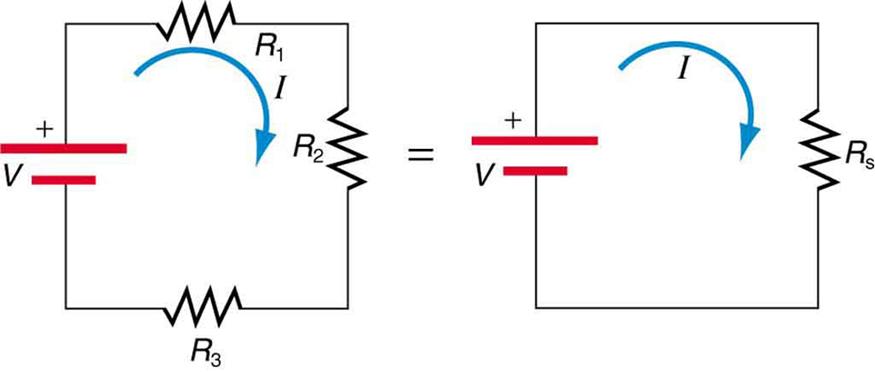
To verify that resistances in series do indeed add, let us consider the loss of electrical power, called a voltage drop, in each resistor in Figure 4.3.
According to Ohm’s law, the voltage drop, across a resistor when a current flows through it is calculated using the equation where equals the current in amps (A) and is the resistance in ohms Another way to think of this is that is the voltage necessary to make a current flow through a resistance
So the voltage drop across is that across is and that across is The sum of these voltages equals the voltage output of the source; that is,
This equation is based on the conservation of energy and conservation of charge. Electrical potential energy can be described by the equation where is the electric charge and is the voltage. Thus, the energy supplied by the source is while that dissipated by the resistors is
Connections: Conservation Laws
The derivations of the expressions for series and parallel resistance are based on the laws of conservation of energy and conservation of charge, which state that total charge and total energy are constant in any process. These two laws are directly involved in all electrical phenomena and will be invoked repeatedly to explain both specific effects and the general behavior of electricity.
These energies must be equal because there is no other source and no other destination for energy in the circuit. Thus, The charge cancels, yielding as stated. (Note that the same amount of charge passes through the battery and each resistor in a given amount of time since there is no capacitance to store charge, there is no place for charge to leak, and charge is conserved.)
Now substituting the values for the individual voltages gives
Note that for the equivalent single series resistance we have
This implies that the total or equivalent series resistance of three resistors is
This logic is valid in general for any number of resistors in series; thus, the total resistance of a series connection is
as proposed. Since all of the current must pass through each resistor, it experiences the resistance of each, and resistances in series simply add up.
Example 4.1 Calculating Resistance, Current, Voltage Drop, and Power Dissipation: Analysis of a Series Circuit
Suppose the voltage output of the battery in Figure 4.3 is and the resistances are and (a) What is the total resistance? (b) Find the current. (c) Calculate the voltage drop in each resistor and show that these add to equal the voltage output of the source. (d) Calculate the power dissipated by each resistor. (e) Find the power output of the source and show that it equals the total power dissipated by the resistors.
Strategy and Solution for (a)
The total resistance is simply the sum of the individual resistances, as given by the equation
Strategy and Solution for (b)
The current is found using Ohm’s law, Entering the value of the applied voltage and the total resistance yields the current for the circuit.
Strategy and Solution for (c)
The voltage—or drop—in a resistor is given by Ohm’s law. Entering the current and the value of the first resistance yields
Similarly,
and
Discussion for (c)
The three drops add to as predicted.
Strategy and Solution for (d)
The easiest way to calculate power in watts (W) dissipated by a resistor in a DC circuit is to use Joule’s law, where is electric power. In this case, each resistor has the same full current flowing through it. By substituting Ohm’s law into Joule’s law, we get the power dissipated by the first resistor as
Similarly,
and
Discussion for (d)
Power can also be calculated using either or where is the voltage drop across the resistor (not the full voltage of the source). The same values will be obtained.
Strategy and Solution for (e)
The easiest way to calculate power output of the source is to use where is the source voltage. This gives
Discussion for (e)
Note, coincidentally, that the total power dissipated by the resistors is also 7.20 W, the same as the power put out by the source. That is,
Power is energy per unit time (watts), so conservation of energy requires the power output of the source to be equal to the total power dissipated by the resistors.
Major Features of Resistors in Series
- Series resistances add
- The same current flows through each resistor in series.
- Individual resistors in series do not get the total source voltage but rather divide it.
Resistors in Parallel
Resistors in Parallel
Figure 4.4 shows resistors in parallel, wired to a voltage source. Resistors are in parallel when each resistor is connected directly to the voltage source by connecting wires having negligible resistance. Each resistor thus has the full voltage of the source applied to it.
Each resistor draws the same current it would if it alone were connected to the voltage source, provided that the voltage source is not overloaded. For example, an automobile’s headlights, radio, and so on are wired in parallel so that they utilize the full voltage of the source and can operate completely independently. The same is true in your house or any building (see Figure 4.4(b)).

To find an expression for the equivalent parallel resistance let us consider the currents that flow and how they are related to resistance. Since each resistor in the circuit has the full voltage, the currents flowing through the individual resistors are and Conservation of charge implies that the total current produced by the source is the sum of these currents.
Substituting the expressions for the individual currents gives
Note that Ohm’s law for the equivalent single resistance gives
The terms inside the parentheses in the last two equations must be equal. Generalizing to any number of resistors, the total resistance of a parallel connection is related to the individual resistances by
This relationship results in a total resistance that is less than the smallest of the individual resistances. This is seen in the next example. When resistors are connected in parallel, more current flows from the source than would flow for any of them individually, so the total resistance is lower.
Example 4.2 Calculating Resistance, Current, Power Dissipation, and Power Output: Analysis of a Parallel Circuit
Let the voltage output of the battery and resistances in the parallel connection in Figure 4.4 be the same as the previously considered series connection: and (a) What is the total resistance? (b) Find the total current. (c) Calculate the currents in each resistor and show that these add to equal the total current output of the source. (d) Calculate the power dissipated by each resistor. (e) Find the power output of the source and show that it equals the total power dissipated by the resistors.
Strategy and Solution for (a)
The total resistance for a parallel combination of resistors is found using the equation below. Entering known values gives
Thus,
Note that in these calculations, each intermediate answer is shown with an extra digit.
We must invert this to find the total resistance This yields
The total resistance with the correct number of significant digits is
Discussion for (a)
is, as predicted, less than the smallest individual resistance.
Strategy and Solution for (b)
The total current can be found from Ohm’s law, substituting for the total resistance. This gives
Discussion for (b)
Current for each device is much larger than for the same devices connected in series (see the previous example). A circuit with parallel connections has a smaller total resistance than the resistors connected in series.
Strategy and Solution for (c)
The individual currents are easily calculated from Ohm’s law since each resistor gets the full voltage. Thus,
Similarly,
and
Discussion for (c)
The total current is the sum of the individual currents.
This is consistent with conservation of charge.
Strategy and Solution for (d)
The power dissipated by each resistor can be found using any of the equations relating power to current, voltage, and resistance since all three are known. Let us use since each resistor gets full voltage. Thus,
Similarly,
and
Discussion for (d)
The power dissipated by each resistor is considerably higher in parallel than when connected in series to the same voltage source.
Strategy and Solution for (e)
The total power can also be calculated in several ways. Choosing and entering the total current yields
Discussion for (e)
Total power dissipated by the resistors is also 179 W.
This is consistent with the law of conservation of energy.
Overall Discussion
Note that both the currents and the powers in parallel connections are greater than for the same devices in series.
Major Features of Resistors in Parallel
- Parallel resistance is found from and it is smaller than any individual resistance in the combination.
- Each resistor in parallel has the same full voltage of the source applied to it. Power distribution systems most often use parallel connections to supply the myriad devices served with the same voltage and to allow them to operate independently.
- Parallel resistors do not each get the total current but rather divide it.
Combinations of Series and Parallel
Combinations of Series and Parallel
More complex connections of resistors are sometimes just combinations of series and parallel. These are commonly encountered, especially when wire resistance is considered. In that case, wire resistance is in series with other resistances that are in parallel.
Combinations of series and parallel can be reduced to a single equivalent resistance using the technique illustrated in Figure 4.5. Various parts are identified as either series or parallel, reduced to their equivalents, and further reduced until a single resistance is left. The process is more time consuming than it is difficult.

The simplest combination of series and parallel resistance, shown in Figure 4.6, is also the most instructive since it is found in many applications. For example, could be the resistance of wires from a car battery to its electrical devices, which are in parallel. and could be the starter motor and a passenger compartment light. We have previously assumed that wire resistance is negligible, but, when it is not, it has important effects, as the next example indicates.
Example 4.3 Calculating Resistance, Drop, Current, and Power Dissipation: Combining Series and Parallel Circuits
Figure 4.6 shows the resistors from the previous two examples wired in a different way—a combination of series and parallel. We can consider to be the resistance of wires leading to and (a) Find the total resistance. (b) What is the drop in ? (c) Find the current through (d) What power is dissipated by

Strategy and Solution for (a)
To find the total resistance, we note that and are in parallel and their combination is in series with Thus, the total (equivalent) resistance of this combination is
First, we find using the equation for resistors in parallel and entering known values
Inverting gives
So the total resistance is
Discussion for (a)
The total resistance of this combination is intermediate between the pure series and pure parallel values and respectively) found for the same resistors in the two previous examples.
Strategy and Solution for (b)
To find the drop in we note that the full current flows through Thus, its drop is
We must find before we can calculate The total current is found using Ohm’s law for the circuit. That is,
Entering this into the expression above, we get
Discussion for (b)
The voltage applied to and is less than the total voltage by an amount When wire resistance is large, it can significantly affect the operation of the devices represented by and
Strategy and Solution for (c)
To find the current through we must first find the voltage applied to it. We call this voltage because it is applied to a parallel combination of resistors. The voltage applied to both and is reduced by the amount so it is
Now the current through resistance is found using Ohm’s law.
Discussion for (c)
The current is less than the 2.00 A that flowed through when it was connected in parallel to the battery in the previous parallel circuit example.
Strategy and Solution for (d)
The power dissipated by is given by
Discussion for (d)
The power is less than the 24.0 W that this resistor dissipated when connected in parallel to the 12.0-V source.
Applying the Science Practices: Circuit Construction Kit (DC only)
Plan an experiment to analyze the effect on currents and potential differences due to rearrangement of resistors and variations in voltage sources. Your experimental investigation should include data collection for at least five different scenarios of rearranged resistors (i.e., several combinations of series and parallel) and three scenarios of different voltage sources.
Practical Implications
Practical Implications
One implication of this last example is that resistance in wires reduces the current and power delivered to a resistor. If wire resistance is relatively large, as in a worn (or a very long) extension cord, then this loss can be significant. If a large current is drawn, the drop in the wires can also be significant.
For example, when you are rummaging in the refrigerator and the motor comes on, the refrigerator light dims momentarily. Similarly, you can see the passenger compartment light dim when you start the engine of your car (although this may be due to resistance inside the battery itself).
What is happening in these high-current situations is illustrated in Figure 4.7. The device represented by has a very low resistance, so when it is switched on, a large current flows. This increased current causes a larger drop in the wires represented by reducing the voltage across the lightbulb (which is ), which then dims noticeably.

Check Your Understanding
Can any arbitrary combination of resistors be broken down into series and parallel combinations? See if you can draw a circuit diagram of resistors that cannot be broken down into combinations of series and parallel.
Solution
No, there are many ways to connect resistors that are not combinations of series and parallel, including loops and junctions. In such cases, Kirchhoff’s rules, to be introduced in Kirchhoff’s Rules, will allow you to analyze the circuit.
Problem-Solving Strategies for Series and Parallel Resistors
- Draw a clear circuit diagram, labeling all resistors and voltage sources. This step includes a list of the knowns for the problem since they are labeled in your circuit diagram.
- Identify exactly what needs to be determined in the problem (identify the unknowns). A written list is useful.
- Determine whether resistors are in series, parallel, or a combination of both series and parallel. Examine the circuit diagram to make this assessment. Resistors are in series if the same current must pass sequentially through them.
- Use the appropriate list of major features for series or parallel connections to solve for the unknowns. There is one list for series and another for parallel. If your problem has a combination of series and parallel, reduce it in steps by considering individual groups of series or parallel connections, as done in this module and the examples. Special note—When finding the reciprocal must be taken with care.
- Check to see whether the answers are reasonable and consistent. Units and numerical results must be reasonable. Total series resistance should be greater, whereas total parallel resistance should be smaller, for example. Power should be greater for the same devices in parallel compared with series and so on.